How to Test an Oxygen Sensor With a Multimeter
You can test many oxygen sensors with a multimeter by checking the sensor signal, heater resistance, power supply, and ground—but the exact method depends on whether the vehicle uses a traditional narrowband O2 sensor or a modern wideband air-fuel ratio sensor.
Learning how to test an oxygen sensor with a multimeter can help you determine whether an O2 sensor is actually faulty before spending money on a replacement. This is especially useful when the check engine light points toward an oxygen-sensor circuit, slow response, heater failure, or rich/lean condition.
A traditional narrowband oxygen sensor can often be tested fairly easily because its signal usually moves between roughly 0.1 and 0.9 volts once the engine is warm and operating in closed loop. You can also test the heater circuit by measuring resistance across the heater terminals and checking that the circuit receives proper power and ground.
Modern wideband oxygen sensors, also called air-fuel ratio sensors, are different. They do not necessarily produce the familiar 0.1-to-0.9-volt switching signal, and testing them with a basic multimeter can be misleading. These sensors are usually diagnosed more accurately with scan-tool data and manufacturer-specific procedures.
Before testing, remember that oxygen sensors are mounted in the exhaust system and can become extremely hot. Work carefully, avoid hot exhaust components, do not short sensor wires, and use vehicle-specific wiring information whenever possible.
This guide explains how to test a traditional O2 sensor signal, check the heater circuit, identify sensor wires, interpret multimeter readings, and recognize situations where the sensor may be good but another engine problem is causing abnormal readings.
How to Test an Oxygen Sensor With a Multimeter
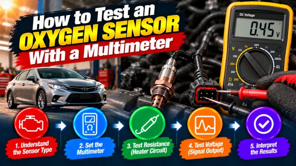
To test a traditional narrowband oxygen sensor with a multimeter, warm the engine to operating temperature, identify the sensor signal wire, set the meter to a low DC-voltage range, back-probe the signal circuit, and observe whether the voltage changes rapidly between roughly 0.1 and 0.9 volts during closed-loop operation.
You should also test the heater circuit by checking:
Heater resistance
Power supply
Ground or control circuit
A complete O2 sensor test should therefore examine both the sensing element and the electrical heater.
Do not rely on one voltage reading alone.
A sensor can produce voltage while still responding too slowly, and a healthy sensor can appear abnormal when the engine itself is actually running rich or lean.
First, Identify What Type of Oxygen Sensor You Have
Before touching the multimeter, determine whether the sensor is:
Narrowband oxygen sensor
or
Wideband air-fuel ratio sensor
This distinction is critical.
Narrowband Oxygen Sensor
A traditional narrowband sensor usually produces a signal that changes sharply around the stoichiometric air-fuel ratio.
On many gasoline engines, the signal typically moves approximately between:
0.1 volt when lean
and
0.9 volt when rich
These sensors can often be evaluated with a digital multimeter.
Wideband Oxygen Sensor
A wideband sensor works differently.
It may use multiple internal circuits and a pump-current system rather than a simple rich/lean voltage switch.
Depending on the vehicle, scan data may display:
Lambda
Air-fuel ratio
Equivalence ratio
Pump current
Manufacturer-specific voltage
A basic multimeter is usually not the best tool for judging wideband sensor performance.
If your vehicle uses a wideband sensor, use factory service information and preferably a scan tool.
Where Is the Oxygen Sensor You Need to Test?
The oxygen sensor is threaded into the exhaust system.
The sensor before the catalytic converter is usually called:
Upstream sensor
Sensor 1
Pre-cat sensor
The sensor after the catalytic converter is commonly called:
Downstream sensor
Sensor 2
If you are diagnosing fuel-control problems such as rough idle, poor gas mileage, or lean/rich operation, the upstream sensor is usually more important.
The downstream sensor mainly monitors catalytic-converter performance.
On V6, V8, and other engines with two cylinder banks, make sure you correctly identify:
Bank 1 Sensor 1
Bank 1 Sensor 2
Bank 2 Sensor 1
Bank 2 Sensor 2
Do not assume Bank 1 is always on the driver’s side.
What Multimeter Should You Use?
Use a digital multimeter with good low-voltage resolution.
A meter capable of accurately reading tenths and hundredths of a volt is suitable for most narrowband O2 sensor tests.
Helpful features include:
DC voltage measurement
Resistance measurement
Continuity testing
Min/max capture if available
High input impedance
A high-impedance meter is preferable because it places very little load on the sensor circuit.
Avoid using an old test light on the signal wire because it can draw too much current and potentially damage sensitive electronics.
What You Need Before Testing
For a typical test, you may need:
Digital multimeter
Back-probe pins or fine test leads
Vehicle wiring diagram
OBD-II scanner if available
Gloves
Eye protection
You may also need a safe way to access the sensor connector.
Do not pierce insulation unless the service procedure specifically permits it. Back-probing the connector is generally preferable.
Safety Before Testing an O2 Sensor
Oxygen sensors operate in one of the hottest areas of the vehicle.
The exhaust manifold, catalytic converter, and exhaust pipe can remain hot long after the engine has been shut off.
Keep:
Hands
Clothing
Meter leads
Wiring
away from hot exhaust surfaces, belts, pulleys, and cooling fans.
If the engine must run during the test, work in a well-ventilated area or outdoors.
Never run a vehicle inside a closed garage because exhaust contains carbon monoxide.
How to Identify Oxygen Sensor Wires
Wire count varies by sensor design.
Older unheated sensors may have only one wire.
Heated sensors commonly have:
Three wires
Four wires
Five or more wires on wideband designs
A common four-wire narrowband sensor may include:
One signal wire
One signal ground
Two heater wires
However, wire colors are not universal.
Do not assume two same-colored wires are always heater wires unless you verify the diagram.
Use a wiring diagram for your exact year, make, model, and engine.
How to Test the O2 Sensor Signal Voltage
This test applies mainly to a traditional narrowband upstream oxygen sensor.
Warm the Engine Fully
The sensor must be hot enough to operate properly.
Start the engine and allow it to reach normal operating temperature.
A short drive is often better than simply letting the vehicle idle because it brings the exhaust and catalytic converter up to temperature more reliably.
Confirm that the engine has entered closed loop if you have a scan tool.
Set the Multimeter to DC Volts
Select a low DC-voltage range if your meter is manually ranged.
A range around 2 volts is ideal if available.
Back-Probe the Signal Wire
Keep the oxygen sensor connected.
Back-probe the signal wire with the positive meter lead.
Connect the negative lead to the sensor signal ground or another approved ground point according to the wiring diagram.
Do not unplug the sensor for this part of the test because the ECM needs to receive the signal while the engine runs.
Observe the Voltage
With the engine warm and operating in closed loop, a conventional upstream narrowband O2 sensor should typically move repeatedly between lower and higher voltage.
A common pattern is approximately:
0.1–0.2 V = lean
0.8–0.9 V = rich
The exact values are less important than whether the sensor responds quickly and repeatedly to mixture changes.
What a Good Narrowband O2 Sensor Reading Looks Like
A healthy upstream narrowband sensor usually does not sit at one fixed voltage.
Instead, the signal repeatedly moves up and down as the ECM adjusts the fuel mixture.
At warm idle, you may see something like:
0.15 V
0.72 V
0.25 V
0.82 V
0.18 V
0.76 V
and so on.
A digital multimeter may not show the switching as smoothly as an oscilloscope, but you should still see frequent changes.
If the voltage switches consistently and responds to deliberate mixture changes, the sensor is likely functioning.
What Does a Constant Low Voltage Mean?
A signal that remains near approximately 0.1 volt or lower may indicate:
A genuinely lean engine
Vacuum leak
Exhaust leak ahead of the sensor
Low fuel pressure
Weak injector flow
Open signal wire
Bad sensor ground
Faulty O2 sensor
This is why a low reading alone does not prove the sensor is bad.
The sensor may simply be correctly reporting a lean mixture.
What Does a Constant High Voltage Mean?
A signal that remains near approximately 0.8–0.9 volt may indicate:
A genuinely rich mixture
Leaking fuel injector
Excessive fuel pressure
Restricted air intake
Faulty MAF-related fueling
Contaminated O2 sensor
Signal shorted to voltage
Again, diagnose the mixture before condemning the sensor.
How to Test O2 Sensor Response to a Rich Condition
One way to evaluate sensor response is to temporarily create a richer mixture using a manufacturer-approved diagnostic method.
For example, a technician may briefly add fuel through a controlled diagnostic procedure or command enrichment with professional equipment.
A good narrowband sensor should respond by moving toward the high-voltage side.
Because introducing fuel improperly can create a fire hazard or damage the engine, DIY testing should avoid spraying flammable chemicals into the intake unless the exact service procedure calls for it.
A scan tool with bidirectional control is a safer diagnostic option when available.
How to Test O2 Sensor Response to a Lean Condition
A technician may create a controlled lean condition by introducing a small, known vacuum leak through an approved diagnostic method.
A healthy narrowband sensor should respond by dropping toward the low-voltage side.
Again, do not disconnect random vacuum hoses on a modern engine unless you understand what that hose controls.
Some lines affect braking, EVAP systems, or other critical functions.
The goal is to verify sensor response, not create additional problems.
How Fast Should an Oxygen Sensor Switch?
A healthy narrowband upstream sensor should respond relatively quickly once fully warmed.
A sensor that changes voltage very slowly may be considered lazy or sluggish.
A slow O2 sensor can still produce both high and low voltage but take too long to transition between them.
This can contribute to:
Poor fuel economy
Higher emissions
Slower fuel correction
Driveability problems
A multimeter can reveal obvious sluggishness, but an oscilloscope or scan tool is much better for accurately measuring switching speed.
Why a Multimeter Is Not Perfect for O2 Signal Testing
A digital multimeter updates its display only a certain number of times per second.
The O2 sensor may change faster than the meter can display.
As a result, a healthy rapidly switching signal can appear averaged or delayed.
An oscilloscope shows the sensor waveform much more clearly.
Still, a multimeter is useful for identifying:
No signal
Fixed high signal
Fixed low signal
Very slow response
Heater problems
Power or ground faults
How to Test the Oxygen Sensor Heater With a Multimeter
Most modern oxygen sensors include a heater.
The heater helps the sensor reach operating temperature quickly.
A failed heater can cause:
Slow closed-loop entry
Cold-start emissions problems
Heater-related trouble codes
Delayed sensor response
You can test the heater by measuring its resistance.
How to Check O2 Sensor Heater Resistance
Turn the engine off.
Allow the exhaust to cool.
Disconnect the oxygen sensor electrical connector.
Identify the two heater terminals using a wiring diagram.
Set the multimeter to ohms.
Measure resistance across the heater terminals.
You should see a finite resistance reading rather than an open circuit.
Exact resistance varies by sensor design and temperature.
A typical heated sensor may show a resistance somewhere in the single-digit to several-dozen-ohm range, but you must use the manufacturer’s specification for your sensor.
Do not condemn a sensor because its resistance does not match a generic internet number.
What Does OL Mean During Heater Resistance Testing?
If your meter displays:
OL
Open
or infinite resistance,
the heater element may be broken internally.
An open heater circuit commonly triggers trouble codes such as:
P0135
P0141
P0155
P0161
depending on bank and sensor location.
However, also verify the wiring and connector before replacing the sensor.
What if Heater Resistance Is Nearly Zero?
An extremely low resistance may indicate an internal short.
Again, compare the reading with the factory specification.
A low-resistance heater can draw excessive current and potentially blow a fuse or set a heater-circuit code.
How to Test O2 Sensor Heater Power
A good heater element will not work if it does not receive power.
With the connector disconnected and ignition in the proper position according to the service procedure, identify the vehicle-side heater power terminal.
Set the multimeter to DC volts.
Connect the negative meter lead to a good ground and the positive lead to the heater power terminal.
Many systems provide approximately battery voltage to the heater circuit.
You might see roughly:
12 volts with the engine off and battery charged
or
13–14+ volts with the engine running
depending on how the circuit is controlled.
Some vehicles do not supply heater power continuously, so use the wiring diagram and service procedure.
How to Test the Heater Ground or Control Side
The other heater wire may be:
Constant ground
ECM-switched ground
Pulse-width-modulated control
depending on the vehicle.
Do not simply assume one wire should always show continuity to chassis ground.
Modern ECMs often control the heater electronically.
The correct test may involve:
Voltage-drop testing
Duty-cycle testing
Current measurement
or scan-tool activation.
Use factory information before applying power or ground directly to any ECM-controlled wire.
How to Check O2 Sensor Wiring
If the sensor itself appears good but you still have a code, inspect the wiring.
O2 sensor wiring lives in a harsh environment.
Common problems include:
Melted insulation
Harness rubbing against exhaust
Corroded connectors
Broken wires
Loose terminals
Oil or water contamination
Rodent damage
Wiring that touches the exhaust can melt internally even when damage is not obvious from above.
Inspect the complete visible harness between the sensor and main wiring loom.
How to Check Signal Ground
A poor signal ground can make a good sensor appear faulty.
Depending on the circuit, you can measure voltage drop between the sensor ground and battery negative while the circuit is operating.
A large voltage difference may indicate unwanted resistance in the ground path.
Do not automatically use chassis ground as a substitute for a dedicated sensor ground during diagnosis.
Some ECM sensor grounds are isolated or shared in specific ways.
How to Test a One-Wire Oxygen Sensor
An older one-wire oxygen sensor uses the single wire as the signal circuit and grounds through its metal body and exhaust system.
To test it, warm the engine fully, set the multimeter to DC volts, connect the positive lead to the sensor signal wire, and connect the negative lead to a good engine ground.
You should observe voltage changes similar to a conventional narrowband sensor.
Because a one-wire sensor has no internal heater, it may take longer to reach operating temperature.
How to Test a Three-Wire Oxygen Sensor
A three-wire sensor usually has:
Two heater wires
One signal wire
The sensor body often provides the signal ground.
Test the signal in the same general way as a narrowband sensor, then test heater resistance across the heater pair.
Verify heater power separately at the vehicle harness.
Again, confirm wire functions using the specific wiring diagram.
How to Test a Four-Wire Oxygen Sensor
A common four-wire narrowband sensor usually contains:
Signal
Signal ground
Heater power/control
Heater ground/control
This design gives the sensor a dedicated signal ground rather than relying on the exhaust system.
Use the dedicated signal ground for the most accurate voltage reading.
A four-wire design is common, but wire colors still vary between manufacturers.
Can You Test an O2 Sensor While It Is Removed?
You can test some basic characteristics with the sensor removed, such as heater resistance.
However, evaluating the sensing element itself is more meaningful while the sensor is installed and exposed to real exhaust gas.
Bench heating an oxygen sensor with a torch is sometimes discussed, but it can damage the sensor, create a fire hazard, and does not reproduce real operating conditions accurately.
In-vehicle testing with live data is usually better.
Can You Test an Oxygen Sensor Without Starting the Engine?
You can test:
Heater resistance
Certain power circuits
Certain ground circuits
Continuity
without running the engine.
However, you cannot properly evaluate the sensor’s exhaust-response behavior without the sensing element being hot and exposed to operating exhaust.
How to Tell if an O2 Sensor Is Bad With a Multimeter
A traditional narrowband sensor becomes more suspicious when several findings agree.
For example, the sensor may be faulty if:
Its heater is open internally.
It receives correct power and ground but does not heat.
Its signal stays fixed despite verified mixture changes.
It responds extremely slowly.
Its output is implausible while fuel and airflow conditions are known to be correct.
The strongest diagnosis comes from combining electrical testing with scan data and engine-condition checks.
O2 Sensor Test Results and What They May Mean
| Multimeter Result | Possible Meaning |
| Signal repeatedly changes roughly 0.1–0.9 V | Narrowband sensor likely responding normally |
| Signal stays near 0 V | Lean condition, wiring fault, poor ground, or bad sensor |
| Signal stays near 0.9 V | Rich condition, wiring issue, or bad sensor |
| Heater shows OL/infinite resistance | Open heater element |
| Heater shows near-zero resistance | Possible shorted heater |
| No heater supply voltage | Fuse, relay, wiring, or ECM control issue |
| Proper heater circuit but slow sensor signal | Aging or contaminated sensor possible |
These readings are diagnostic clues, not absolute verdicts.
How to Test Bank 1 Sensor 1
Bank 1 Sensor 1 is the upstream sensor on the side of the engine containing cylinder number 1.
Because it is upstream, it typically plays an important role in fuel control.
For a narrowband design, test:
Signal switching
Heater resistance
Power supply
Ground
Wiring integrity
If it is a wideband air-fuel sensor, do not apply narrowband voltage expectations.
How to Test Bank 1 Sensor 2
Bank 1 Sensor 2 is usually located after the catalytic converter.
A downstream narrowband sensor often shows a steadier signal than the upstream sensor when the catalytic converter is functioning properly.
Do not expect Bank 1 Sensor 2 to switch exactly like Bank 1 Sensor 1.
If the downstream signal closely mirrors the upstream sensor, the issue may involve catalytic-converter efficiency rather than a failed sensor.
What if Both Upstream and Downstream Sensors Look the Same?
If both signals switch rapidly in a similar pattern, several possibilities exist.
The catalytic converter may have reduced oxygen-storage capacity.
There may be an exhaust leak.
The downstream sensor may be located differently than expected.
The scan or meter interpretation may be incorrect.
Do not automatically replace the downstream sensor.
Codes such as P0420 require diagnosis of the entire catalyst-monitoring system.
Can a Vacuum Leak Make a Good O2 Sensor Look Bad?
Yes.
A vacuum leak adds unmetered air to the engine.
The upstream oxygen sensor sees extra oxygen in the exhaust and reports a lean condition.
The voltage may remain low for long periods.
The sensor is not necessarily defective—it may be accurately reporting the lean mixture.
This is one of the most common reasons O2 sensors get replaced unnecessarily.
Can an Exhaust Leak Affect O2 Sensor Testing?
Yes.
A leak before or close to the upstream sensor can introduce outside air into the exhaust.
The sensor may then report lean even if the combustion mixture is normal.
Check for:
Cracked exhaust manifold
Leaking manifold gasket
Loose sensor threads
Damaged flex pipe
Leaking flange
before condemning a low-reading sensor.
Can a Misfire Affect O2 Readings?
Yes.
When a cylinder misfires, oxygen may pass through the cylinder without being consumed.
The oxygen sensor sees that oxygen and may report lean.
That means a bad:
Spark plug
Ignition coil
Fuel injector
Compression problem
can produce low O2 voltage even when the sensor itself is healthy.
If misfire codes are present, diagnose the misfire first.
Can a Rich Engine Make the O2 Sensor Stay High?
Yes.
A leaking injector, excessive fuel pressure, faulty MAF sensor, or other fuel-control problem can create genuinely rich exhaust.
The O2 sensor may remain near the high-voltage side because it is correctly detecting low oxygen in the exhaust.
Again, sensor output must be interpreted in context.
How a Scan Tool Improves O2 Sensor Diagnosis
A multimeter is useful, but a scan tool gives you much more context.
You can compare:
O2 sensor signal
Short-term fuel trim
Long-term fuel trim
Closed-loop status
Coolant temperature
MAF airflow
Misfire counters
Commanded air-fuel ratio
A sensor that appears lean while fuel trims are strongly positive may be accurately reporting a true lean condition.
This is why combining multimeter readings with scan data is much more reliable than using either one alone.
Can You Test an O2 Sensor With Resistance Alone?
No.
Resistance testing is mainly useful for the heater element.
The sensing element itself should not normally be judged by measuring resistance across random terminals.
Doing so can produce meaningless results and, on some sensor types, may risk damage.
Use voltage or scan-data testing for the sensing signal and resistance testing only where the service procedure specifies it.
Should You Pierce the O2 Sensor Wire?
Avoid it if possible.
Piercing insulation can allow:
Water
Salt
Corrosion
to enter the wire later.
Use back-probe pins at the connector whenever possible.
If wire piercing is absolutely necessary during professional diagnosis, the insulation should be properly sealed afterward.
Can You Use Continuity Mode on an Oxygen Sensor?
Continuity mode is useful for checking wiring, but not for judging the O2 sensing element.
You may use it to verify whether a wire between the sensor connector and ECM is open, provided the circuit is safely disconnected and the service procedure permits it.
Do not perform continuity or resistance testing on a powered circuit.
Common Mistakes When Testing an Oxygen Sensor With a Multimeter
One common mistake is testing the sensor while the engine is still cold. A narrowband sensor may produce little useful signal until it reaches operating temperature.
Another mistake is confusing a wideband sensor with a narrowband sensor. Expecting a wideband sensor to switch between 0.1 and 0.9 volts can lead to an incorrect diagnosis.
A third mistake is assuming a low or high voltage proves the sensor itself is bad. The sensor may be correctly reporting an actual lean or rich engine condition.
Finally, wire identification matters. Accidentally applying voltage to a signal circuit or shorting an ECM-controlled wire can damage expensive electronics.
When Should You Replace the Oxygen Sensor?
Replace the sensor when testing confirms an internal fault.
That may include:
Open heater element
Failed sensing element
Very slow response
No response to verified mixture changes
Internal short
Severe contamination
Before replacement, correct any underlying problem such as:
Oil burning
Coolant contamination
Rich operation
Misfire
Exhaust leak
Otherwise, the new sensor may fail prematurely or continue showing abnormal readings.
FAQs About How to Test an Oxygen Sensor With a Multimeter
What Voltage Should an Oxygen Sensor Show?
A traditional narrowband upstream oxygen sensor often moves roughly between 0.1 and 0.9 volts once fully warm and operating in closed loop.
Wideband sensors use different electrical behavior and should not be tested using this same voltage range.
How Do I Know if My O2 Sensor Is Bad With a Multimeter?
A sensor becomes suspect if it receives proper power and ground but produces no signal, responds extremely slowly, fails to react to verified rich and lean changes, or has an open heater circuit.
Always rule out wiring and engine-condition problems first.
Can I Test an O2 Sensor Without Removing It?
Yes. In fact, signal testing is usually best performed with the sensor installed and connected while the engine is operating.
You can back-probe the sensor connector to measure the signal.
What Resistance Should an O2 Sensor Heater Have?
The exact resistance depends on sensor design and temperature.
Many heated sensors measure somewhere in the single-digit to several-dozen-ohm range, but you should use the factory specification rather than a generic number.
What Does 0 Volts From an O2 Sensor Mean?
It may indicate an open circuit, poor ground, cold sensor, lean engine condition, or failed sensor.
One zero reading is not enough to identify the cause.
What Does 0.9 Volts From an O2 Sensor Mean?
On a traditional narrowband sensor, around 0.9 volts generally indicates a rich exhaust condition.
If the signal stays high continuously, determine whether the engine is actually rich before replacing the sensor.
Can a Bad Heater Make the O2 Sensor Read Wrong?
Yes.
A failed heater can prevent the sensor from reaching its normal operating temperature quickly, especially during idle or cold conditions.
This can delay or disrupt proper sensor response.
Can I Test a Wideband O2 Sensor With a Multimeter?
Only partially.
You can often test heater power, resistance, and wiring, but the actual sensing function is usually better evaluated with scan-tool data and manufacturer-specific procedures.
Conclusion
The overall method for how to test an oxygen sensor with a multimeter depends first on identifying the sensor type. A traditional narrowband upstream O2 sensor can often be evaluated by warming the engine, back-probing the signal circuit, and checking for rapid voltage changes roughly between 0.1 and 0.9 volts. The heater can also be checked by measuring resistance and verifying its power and control circuits.
The most important diagnostic lesson is that an abnormal O2 reading does not automatically mean the sensor is bad. A vacuum leak, exhaust leak, misfire, fuel-pressure problem, injector fault, or rich-running engine can make a perfectly good sensor stay low or high.
Use the multimeter together with vehicle-specific wiring information and, whenever possible, scan-tool data such as fuel trims and closed-loop status. If the sensor has correct wiring and heater operation but fails to respond properly to verified mixture changes, replacement becomes much more justified. For wideband air-fuel sensors, rely on the manufacturer’s test procedure rather than trying to interpret them like a traditional 0.1-to-0.9-volt O2 sensor.