How to Check Oxygen Sensor With a Scanner: Step-by-Step Guide
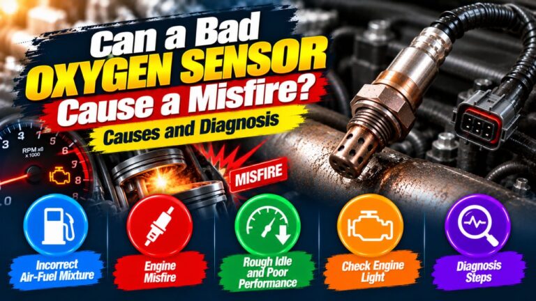
A check engine light or oxygen sensor trouble code does not automatically mean the oxygen sensor itself has failed. Vacuum leaks, exhaust leaks, fuel-pressure problems, misfires, wiring faults, and even a failing catalytic converter can all create readings that make an O2 sensor look suspicious.
One of the best ways to investigate the problem is with an OBD-II scan tool that displays live data. Instead of relying only on stored trouble codes, live data lets you watch how the oxygen sensor reacts while the engine is actually running.
To check an oxygen sensor with a scanner, warm the engine to operating temperature, open the scanner’s live-data menu, locate the upstream and downstream O2 or air-fuel sensor readings, and watch how they respond at idle and when engine speed changes. A traditional upstream narrowband sensor should normally switch quickly between rich and lean, while a wideband sensor must be evaluated using the manufacturer’s specified data rather than the traditional 0.1–0.9 volt rule.
Learning how to check oxygen sensor with a scanner also requires knowing which sensor you are looking at. Upstream and downstream sensors behave differently, and wideband air-fuel ratio sensors should not be interpreted like conventional narrowband oxygen sensors.
This guide explains how to identify the correct sensor, read live O2 data, interpret voltage and fuel trims, compare upstream and downstream sensors, and distinguish a genuinely bad sensor from another engine problem.
How to Check Oxygen Sensor With a Scanner
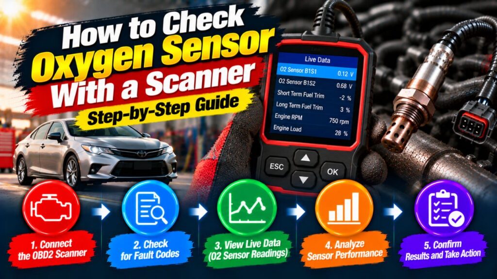
The basic process for how to check oxygen sensor with a scanner is to connect an OBD-II scan tool, bring the engine to operating temperature, open live data, select the relevant oxygen sensor parameters, and observe how the readings respond while the engine operates under different conditions.
Before testing, confirm that your scanner supports live data. A basic code reader that only reads and clears diagnostic trouble codes cannot provide enough information for this test.
You should also determine whether your vehicle uses a conventional narrowband oxygen sensor or a wideband air-fuel ratio sensor in the upstream position, because the expected readings are different.
What You Need to Test an Oxygen Sensor
For most vehicles, you need an OBD-II scanner capable of displaying real-time engine data.
Useful scanner capabilities include:
- Live O2 sensor data
- Short-term fuel trim
- Long-term fuel trim
- Engine coolant temperature
- RPM
- Freeze-frame data
A more advanced scanner may also show air-fuel equivalence ratio, lambda, sensor current, heater status, and manufacturer-specific parameters.
You do not necessarily need an expensive professional scan tool for basic testing, but the scanner must show the data your vehicle provides.
Connect the Scanner to the OBD-II Port
The OBD-II diagnostic connector is normally located under the dashboard near the driver’s side.
With the vehicle safely parked, connect the scanner to the diagnostic port.
Turn the ignition on if required by your scanner, then start the engine.
Open the scanner menu and look for options such as:
Live Data, Data Stream, Powertrain Data, or Engine Data.
The exact wording depends on the scanner.
Warm the Engine Before Testing
A cold oxygen sensor can give misleading results.
Most oxygen sensors need to reach a high operating temperature before they work normally. Modern heated sensors warm up quickly, but testing is still more reliable after the engine reaches normal operating temperature and enters closed-loop fuel control.
Check coolant temperature on the scanner if available.
Once the engine is warm, look for a parameter indicating:
Closed Loop, Fuel System CL, or similar wording.
When the ECM enters closed loop, it begins actively using oxygen sensor feedback for fuel control.
Identify the Correct Oxygen Sensor
A vehicle may have two, four, or even more oxygen sensors.
They are usually identified by bank and sensor number.
Bank 1 Sensor 1
Bank 1 Sensor 1, often abbreviated B1S1, is the upstream sensor on the engine bank containing cylinder number 1.
It is located before the catalytic converter.
Bank 1 Sensor 2
Bank 1 Sensor 2, or B1S2, is located after the catalytic converter on Bank 1.
Bank 2 Sensor 1
On V-type engines, B2S1 is the upstream sensor on the opposite cylinder bank.
Bank 2 Sensor 2
B2S2 is the downstream sensor on Bank 2.
For most fuel-control diagnosis, you should pay particular attention to Sensor 1, because the upstream sensor has the greatest influence on fuel mixture.
Upstream vs. Downstream Sensor Behavior
Do not expect upstream and downstream sensors to display identical patterns.
The upstream sensor sees exhaust gases directly from the engine and should respond quickly to mixture changes.
The downstream sensor sees exhaust after it passes through the catalytic converter, so its signal normally changes more slowly and is generally steadier when the converter is operating properly.
This difference is important when reading scanner graphs.
How to Read a Narrowband Oxygen Sensor With a Scanner
A traditional heated narrowband oxygen sensor commonly produces a voltage of roughly 0.1 to 0.9 volts once fully warmed.
Lower voltage generally represents a leaner exhaust condition.
Higher voltage generally represents a richer exhaust condition.
During normal closed-loop operation, an upstream narrowband sensor often moves rapidly between lower and higher voltage.
You may see values approximately like:
0.15 V → 0.75 V → 0.25 V → 0.85 V → 0.20 V
The exact numbers are less important than whether the sensor responds quickly and repeatedly as the ECM adjusts fuel delivery.
What Is a Normal Upstream O2 Sensor Reading?
For a conventional narrowband upstream sensor, you usually want to see the voltage continuously moving between roughly lean and rich values rather than remaining fixed.
A properly functioning sensor may switch repeatedly across approximately 0.45 volts during closed-loop operation.
The actual frequency varies with:
- Engine speed
- Engine load
- Sensor design
- ECM strategy
Do not judge a sensor only by one snapshot reading.
Watching the graph for several seconds is far more useful.
Use Graph Mode if Your Scanner Has It
Graphing makes oxygen sensor testing much easier.
Instead of looking at changing numbers, you can see the sensor waveform.
A healthy upstream narrowband sensor normally produces a repeating pattern as it moves rich and lean.
A graph makes it easier to recognize:
- Fast switching
- Slow response
- Sensor stuck rich
- Sensor stuck lean
- Flat or inactive signal
If your scanner supports graphing, use it whenever possible.
What Does a Sensor Stuck Lean Look Like?
A narrowband sensor that stays at a very low voltage for an extended period may appear stuck lean.
However, this does not automatically mean the oxygen sensor is bad.
The engine may actually be running lean because of:
- Vacuum leak
- Intake leak
- Low fuel pressure
- Dirty injector
- Exhaust leak ahead of sensor
The scanner only shows what the sensor reports.
You must determine whether the reading is accurate or false.
What Does a Sensor Stuck Rich Look Like?
A sensor that remains at high voltage may appear stuck rich.
Possible causes include:
- Excessive fuel pressure
- Leaking injector
- Rich fuel mixture
- EVAP purge problem
- Engine oil entering combustion
- Faulty sensor
Again, do not replace the sensor based on high voltage alone.
The engine may genuinely be running rich.
How to Perform a Simple Response Test
A good oxygen sensor should respond when the air-fuel mixture changes.
With the engine warm, watch the upstream sensor live data while briefly changing engine speed.
A healthy sensor should normally react quickly.
If the sensor remains almost completely unchanged despite a noticeable change in engine operating conditions, it deserves further testing.
Professional technicians may deliberately create controlled rich or lean conditions, but DIY testing should avoid introducing flammable chemicals or creating unsafe vacuum leaks.
The scanner itself, combined with fuel-trim data and normal throttle changes, often provides enough information for preliminary diagnosis.
Check Short-Term Fuel Trim Alongside the O2 Sensor
One of the best ways to interpret oxygen sensor data is to look at short-term fuel trim, or STFT.
Fuel trim shows how the ECM is changing fuel delivery in response to sensor feedback.
Positive fuel trim means the ECM is adding fuel.
Negative fuel trim means the ECM is removing fuel.
For example, if the O2 sensor reports lean and STFT becomes strongly positive, the ECM is trying to correct the lean condition by adding fuel.
That does not prove the O2 sensor is bad. It may indicate that the engine truly has excess air or insufficient fuel.
Check Long-Term Fuel Trim Too
Long-term fuel trim, or LTFT, represents corrections the ECM has learned over a longer period.
A consistently large positive LTFT may point toward a persistent lean condition.
A large negative LTFT can suggest the ECM has been compensating for a rich condition.
Exact acceptable ranges vary by vehicle, but fuel trims close to zero are generally more normal than large corrections.
Do not diagnose an O2 sensor from fuel trims alone. Use them together with sensor behavior and other engine data.
Narrowband O2 Sensor Example
Suppose the engine is warm and operating in closed loop.
You observe:
B1S1 rapidly moving between approximately 0.1 and 0.9 volts.
STFT moving slightly positive and negative around zero.
That generally indicates the upstream sensor is responding and the ECM is actively controlling fuel mixture.
Now suppose B1S1 remains around 0.1 volts while STFT climbs strongly positive.
That could indicate a lean condition, but you still need to determine whether the sensor is correctly reporting an actual lean mixture.
How to Check a Wideband Oxygen Sensor With a Scanner
Many modern vehicles use a wideband oxygen sensor, often called an air-fuel ratio sensor, in the upstream position.
Do not test these sensors using the traditional narrowband 0.1–0.9 volt switching rule.
Wideband sensors may be displayed by the scanner as:
- Lambda
- Equivalence ratio
- AFR
- A/F sensor current
- Sensor voltage
- Pump current
The exact reading depends heavily on manufacturer and scanner.
Reading Lambda on a Scanner
If your scanner displays lambda, a value near 1.00 usually represents a mixture near the stoichiometric target for gasoline during normal closed-loop operation.
A value above or below 1.00 indicates movement away from that target, but the exact interpretation depends on the parameter and vehicle.
Because wideband systems vary, use the service information for the specific vehicle before condemning the sensor.
Why Wideband Sensor Voltage Can Be Confusing
Some wideband sensors may display a voltage around 2 to 3 volts or another manufacturer-specific value.
This does not mean the sensor is bad simply because it does not move between 0.1 and 0.9 volts.
The scanner may be showing a calculated parameter rather than the raw sensing element voltage.
This is one of the most common mistakes people make when diagnosing newer O2 sensors.
How to Check the Downstream Oxygen Sensor With a Scanner
After checking the upstream sensor, observe the downstream sensor.
On a vehicle with a healthy catalytic converter and conventional narrowband sensors, the downstream sensor should usually display a steadier pattern than the upstream sensor.
The upstream sensor may switch rapidly, while the downstream sensor changes more slowly.
If both signals closely mirror one another, the catalytic converter may not be storing oxygen effectively.
However, this is not enough by itself to condemn the catalytic converter.
Exhaust leaks, engine mixture problems, sensor faults, and vehicle-specific catalyst-monitor strategies must also be considered.
Can You Diagnose a Catalytic Converter From O2 Sensor Graphs?
O2 sensor graphs can provide useful clues.
A common pattern is:
Upstream sensor: frequent switching.
Downstream sensor: relatively stable.
When the downstream waveform begins copying the upstream waveform closely, converter efficiency may be reduced.
But catalyst diagnosis should also consider trouble codes such as P0420 or P0430, exhaust leaks, fuel-control problems, and the condition of both sensors.
Replacing a catalytic converter based only on one graph is risky.
What If the O2 Sensor Reading Does Not Change?
An oxygen sensor that remains completely fixed may have a problem, but several possibilities exist.
The sensor could be:
- Electrically disconnected
- Not hot enough
- Suffering from a heater failure
- Contaminated
- Internally damaged
The issue could also be in the wiring or ECM circuit.
Before replacing the sensor, inspect the connector and related trouble codes.
Check O2 Sensor Heater Codes
Modern oxygen sensors usually contain an internal heater.
The heater helps the sensor reach operating temperature quickly.
If the heater circuit fails, the scanner may show codes such as P0135, P0141, or related bank-specific codes depending on the vehicle.
A heater fault does not necessarily mean the sensing element itself has failed.
Possible causes include:
- Blown fuse
- Damaged wiring
- Poor connector
- Failed heater element
- Power or ground problem
Diagnose the heater circuit before automatically replacing the sensor.
Common Oxygen Sensor Trouble Codes
Different faults can produce different OBD-II codes.
For example:
P0130-series codes commonly relate to Bank 1 oxygen sensor circuits.
P0150-series codes commonly relate to Bank 2 sensor circuits.
You may also see codes describing:
- Slow response
- No activity
- Heater failure
- High voltage
- Low voltage
A trouble code tells you what the ECM detected. It does not always tell you which component caused the condition.
How a Vacuum Leak Can Fool O2 Sensor Diagnosis
A vacuum leak lets unmetered air enter the engine.
This can make the engine run lean.
The upstream O2 sensor detects excess oxygen in the exhaust and correctly reports a lean condition.
If you replace the O2 sensor without repairing the vacuum leak, the new sensor will report the same thing.
This is why fuel trims are so useful.
Large positive fuel trims, especially at idle, may suggest an intake or vacuum leak rather than a sensor fault.
How an Exhaust Leak Can Affect O2 Readings
An exhaust leak ahead of the oxygen sensor can draw outside air into the exhaust stream.
The additional oxygen can make the sensor report lean.
Leaks around:
- Exhaust manifold
- Flange connections
- Sensor bung
- Exhaust gasket
can interfere with diagnosis.
Inspect for exhaust leaks before condemning a sensor based on a persistent lean reading.
Can a Misfire Make the O2 Sensor Look Bad?
Yes.
A misfire can send unused oxygen into the exhaust.
The sensor sees that oxygen and may indicate a lean condition.
The engine computer may then add fuel even though lack of fuel was not the original problem.
If you have both misfire codes and oxygen sensor abnormalities, diagnose the misfire rather than assuming the sensor caused it.
Compare Both Banks on a V6 or V8
Vehicles with two cylinder banks provide a useful comparison.
If Bank 1 Sensor 1 and Bank 2 Sensor 1 are the same type, compare their behavior under similar operating conditions.
If one responds quickly and the other remains unusually slow or fixed, that difference can help identify a problem.
However, bank-specific vacuum leaks, injector issues, or exhaust leaks can also create different readings.
Use the comparison as diagnostic evidence, not absolute proof.
What Does a Slow Oxygen Sensor Look Like?
An aging narrowband oxygen sensor may still move rich and lean but respond much more slowly than expected.
You may notice delayed transitions rather than fast switching.
A slow upstream sensor can reduce the accuracy of fuel control and may trigger a slow-response code.
Comparing identical sensors on opposite banks can be useful when available.
Should You Rev the Engine During O2 Sensor Testing?
A brief increase in engine RPM can help you observe sensor response.
You do not need to repeatedly race the engine.
With the vehicle safely in Park or Neutral and the parking brake applied, briefly raising RPM can show whether the sensor responds as exhaust flow and operating conditions change.
Follow safe workshop practices and avoid testing in an enclosed area because exhaust gases contain carbon monoxide.
How to Know If the Oxygen Sensor Is Actually Bad
A sensor becomes more suspicious when several pieces of evidence agree.
For example, you might find that the sensor remains inactive after the engine is fully warm, does not react when operating conditions change, has appropriate power and ground to its heater, and other engine problems have been ruled out.
A scanner alone can provide strong clues, but electrical testing may still be required.
That can include checking:
- Heater power
- Ground
- Wiring continuity
- Connector condition
For advanced wideband systems, manufacturer-specific diagnostic procedures are particularly important.
Can a Scanner Tell You Which O2 Sensor Is Bad?
Sometimes it can tell you which sensor has an abnormal circuit or reading, but it cannot always prove the sensor itself is the failed component.
For example, a code for Bank 1 Sensor 1 low voltage could be caused by:
- Failed sensor
- Wiring problem
- Exhaust leak
- Genuine lean condition
The scanner identifies where the ECM detected the problem. Diagnosis determines why it occurred.
Can a Cheap OBD-II Scanner Test Oxygen Sensors?
Yes, if it supports live data.
A basic inexpensive scanner may show:
- O2 sensor voltage
- STFT
- LTFT
- RPM
- Coolant temperature
That can be enough for basic narrowband diagnosis.
More advanced vehicles using wideband sensors may benefit from a better scanner that displays manufacturer-specific air-fuel sensor parameters and graphing.
Should You Replace an O2 Sensor Based Only on a Code?
No.
A trouble code should be treated as the starting point of diagnosis.
For example, an O2 sensor lean code may simply mean the sensor is accurately detecting a lean engine.
Replacing the sensor without checking:
- Vacuum leaks
- Fuel pressure
- Exhaust leaks
- Misfires
- Wiring
can waste money and leave the original problem unchanged.
Common Mistakes When Checking O2 Sensors With a Scanner
One common mistake is testing a cold engine. Sensor behavior is easier to interpret after the engine reaches operating temperature and enters closed loop.
Another mistake is applying narrowband voltage rules to a wideband air-fuel ratio sensor.
It is also easy to assume a low O2 voltage means a failed sensor when the engine is actually running lean.
The best diagnosis combines oxygen sensor data with fuel trims, engine operating conditions, trouble codes, and physical inspection.
FAQs About How to Check Oxygen Sensor With a Scanner
How do I check an O2 sensor with an OBD2 scanner?
Connect a scanner that supports live data, warm the engine, confirm closed-loop operation, and monitor the appropriate upstream O2 or air-fuel sensor parameter. Look for normal response rather than relying only on stored codes.
What voltage should an oxygen sensor show on a scanner?
A traditional narrowband sensor commonly moves roughly between 0.1 and 0.9 volts when warm.
Wideband air-fuel ratio sensors use different values and must be interpreted according to the vehicle’s specifications.
Should an upstream O2 sensor voltage keep changing?
A conventional narrowband upstream sensor normally switches repeatedly between lean and rich during closed-loop operation.
A nearly fixed value may require further diagnosis.
Should the downstream oxygen sensor switch like the upstream sensor?
Usually not.
With a healthy catalytic converter, the downstream sensor is generally steadier than the upstream sensor.
Can fuel trim tell me if the oxygen sensor is bad?
Fuel trim can provide important clues, but it cannot by itself prove an O2 sensor has failed.
Large corrections can also result from vacuum leaks, fuel delivery problems, exhaust leaks, or other faults.
How do I test a wideband oxygen sensor with a scanner?
Look for lambda, equivalence ratio, air-fuel ratio, or manufacturer-specific sensor data.
Do not apply the traditional 0.1–0.9 volt narrowband test unless the service information confirms that is appropriate.
Can a scanner show a bad oxygen sensor without a check engine light?
Yes.
Live data may reveal a sensor that responds unusually slowly or inconsistently before the ECM sets a trouble code.
Can I diagnose an oxygen sensor without a multimeter?
Often you can get strong diagnostic information from live scan data alone.
However, electrical testing may still be necessary when you need to verify heater power, ground, or wiring integrity.
Conclusion
The practical answer to how to check oxygen sensor with a scanner is to use live data rather than relying only on trouble codes. Warm the engine, confirm it is operating in closed loop, identify the correct Bank and Sensor position, and watch how the upstream sensor responds as engine conditions change.
For a traditional narrowband upstream O2 sensor, a healthy signal normally moves rapidly between richer and leaner readings, often within roughly 0.1 to 0.9 volts. A downstream sensor should generally be steadier because it monitors exhaust after the catalytic converter. Wideband air-fuel ratio sensors are different and must be interpreted using lambda, equivalence ratio, current, or other manufacturer-specific scanner data rather than traditional narrowband voltage rules.
Most importantly, do not condemn an oxygen sensor simply because the scanner shows a lean, rich, or O2-related code. Compare the sensor reading with short-term and long-term fuel trims, check for vacuum and exhaust leaks, consider misfires and fuel-delivery problems, and inspect wiring when necessary. Using the scanner this way helps determine whether the oxygen sensor is actually faulty or is simply reporting another engine problem correctly.